Installation Audio Art Car Hi-Fi
Here’s described the installation of the Audio Art Car Hi-Fi. For an even better result in execution and end result, it was especially paid attention to some details.
RS Center distributes and installs Car Hi-Fi components from Audio Art. Audio Art sells and used not only chosen Car Audio products, but also produces its own components under the name Scustic. Here it comes to use the smallest music system: The Plug & Play solution consisting of:
- Amplifier Audiotechnik Fischer PP82DSP
- Bass reflex subwoofer Audiotechnik Fischer PP 7S D. The basses were exchanged against two 16cm Kicker Comp RT 67 Chassis.
- Scustic 2-way system consisting of the Audiotechnik Fischer Helix 13cm woofers P 205 and tweeter and crossover from Scustic
- iPod Classic 6.5G 160GB “Renault Sport Mégane R.S. Trophy N°0082”, yellow anodized
- RS Center iPod console in the armrest
- Optima Yellow Top 4.2 55Ah 765A starter battery
All cables and speaker cables remain OEM. Without replacing the bass chassis of the subwoofer, it wouldn’t be necessary to have an external power supply directly from the starter battery for the amplifier. Thus, this installation requires only the installation of the 2-way system, insulated, the amplifier is connected by Y-adapter between OEM radio and OEM speaker cables, and the only harness to connect the subwoofer to the rear.
The specifications for this music system were that no additional changes to the original parts, such as additional holes or cuts, had to be carried out on the car, so that no parts would have to be replaced or repaired after dismantling. In addition, all components that can be seen, especially the loudspeaker system, should be installed inconspicuously, invisibly, or at the originally intended installation locations.
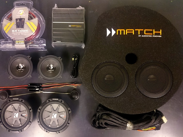
The components.
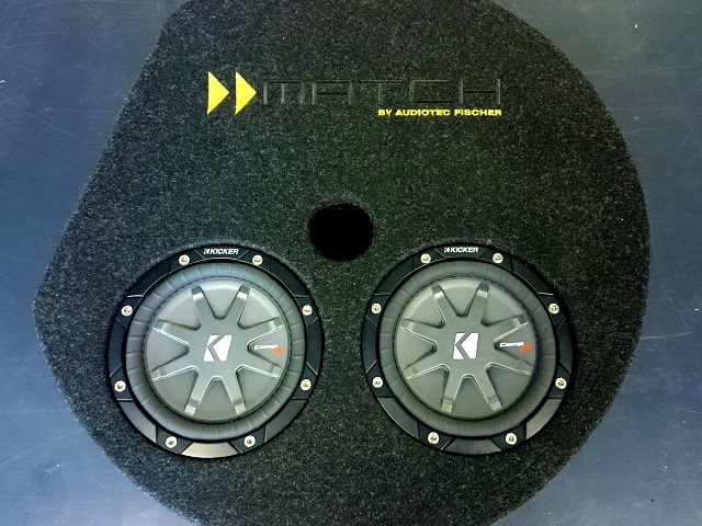
On the subwoofer the two chassis were replaced and the embroidery changed from orange / white to yellow / black.
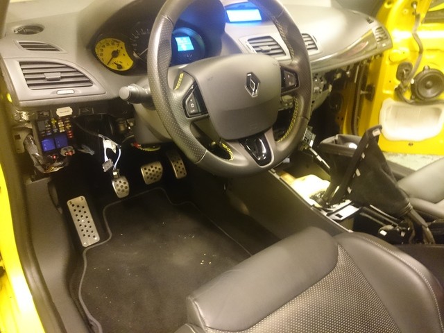
The interior was as far as necessary decomposed.
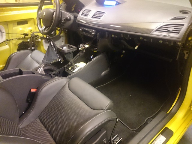
The view from the right side.
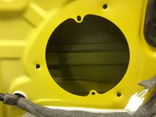
The OEM speakers were removed.
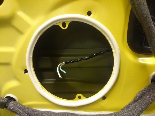
It was attached sealing tape.
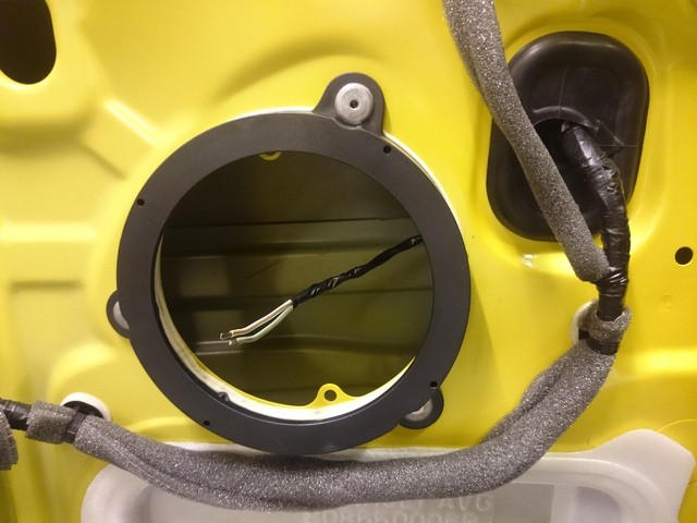
The adapter rings were riveted and the speakers harness placed behind the door sheet.
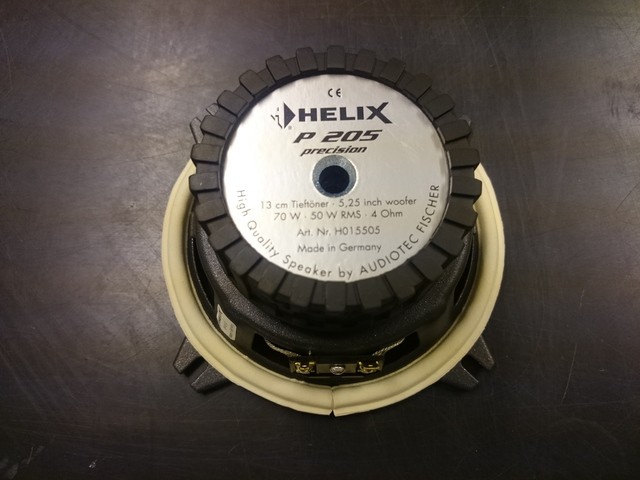
The mid-range speakers were also provided with sealing tape.
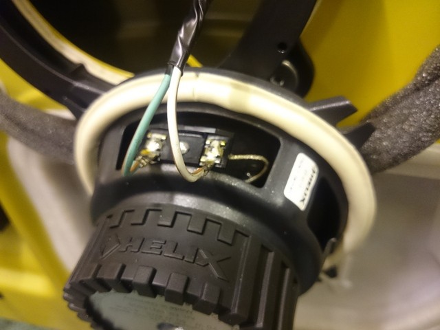
The loudspeaker cables were soldered directly to the mid-range speakers.
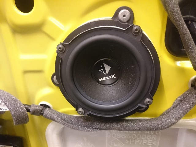
The mid-range speakers were mounted.
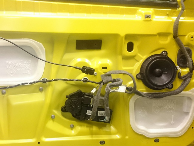
The door panels can be re-assembled.
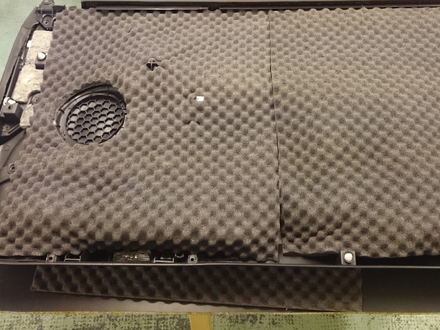
The door panels were insulated from the inside.
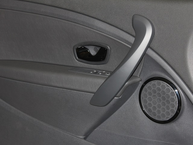
The door panels were installed and from the outside, of course, nothing can be seen.
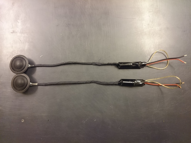
The Scoustic tweeters and crossovers are ready for the installation.
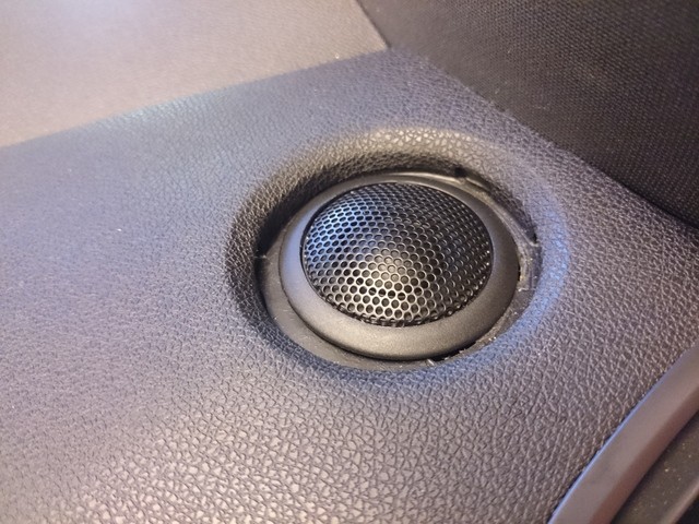
The Scoustic tweeters fit into the OEM installation location without processing the dashboard.
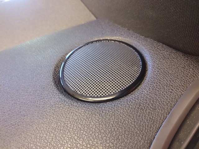
Also the OEM tweeter covers still fit without adaptations.
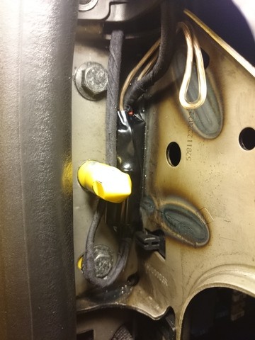
The crossovers were located on the side of the dashboard. So they remain easily accessible.
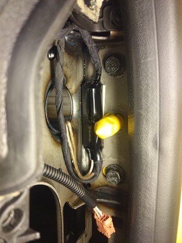
View from the right side.
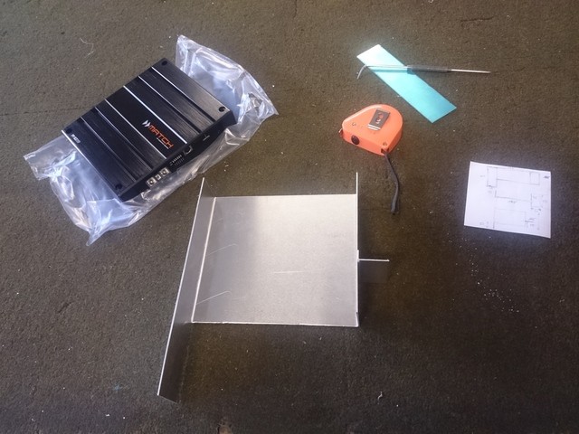
For mounting the amplifier, it was made of an aluminum bracket.
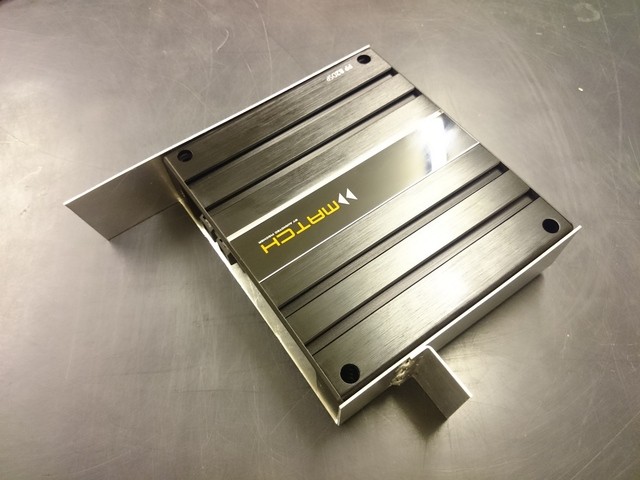
The amplifier with aluminium bracket is ready to install.
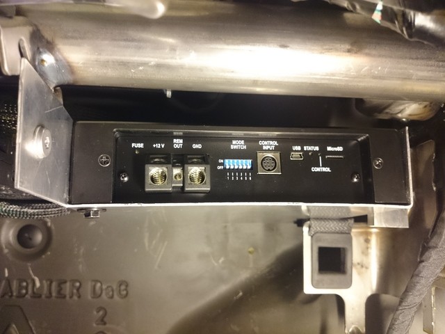
The amplifier with aluminium bracket was mounted.
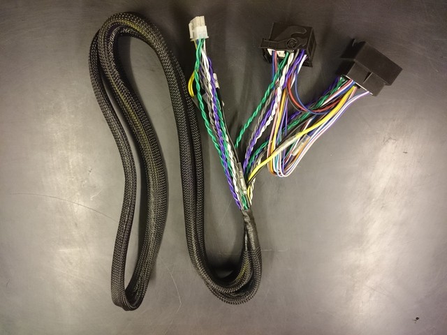
The Y-adapter is inserted between the OEM radio and the amplifier.
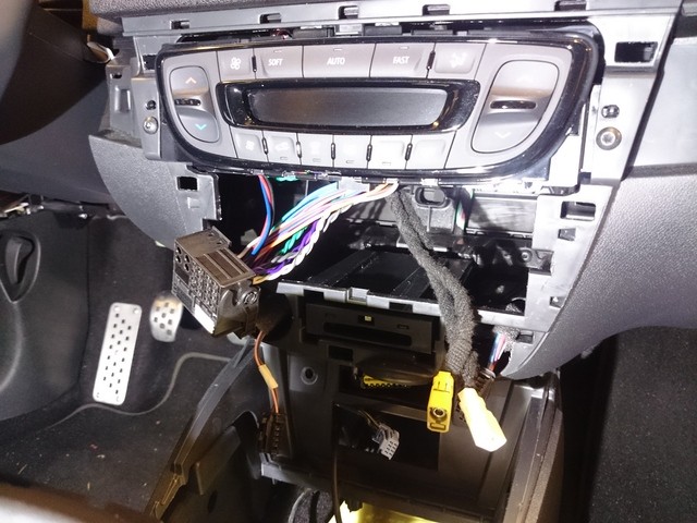
The OEM radio has been removed and the Y-adapter has been installed.
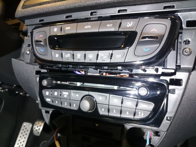
The radio was re-installed.
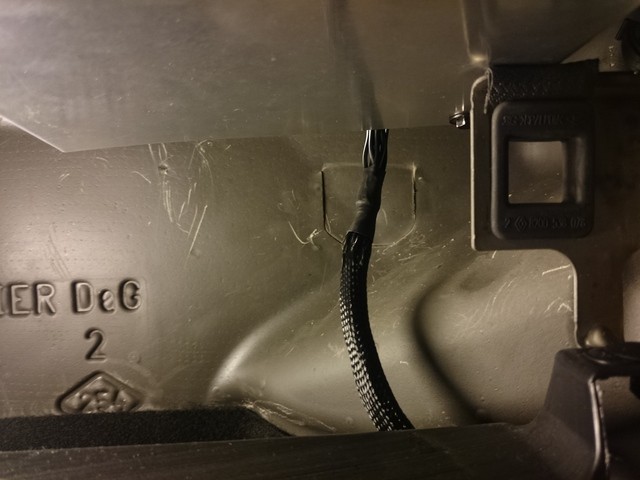
The harness between amplifier and subwoofer was mounted.
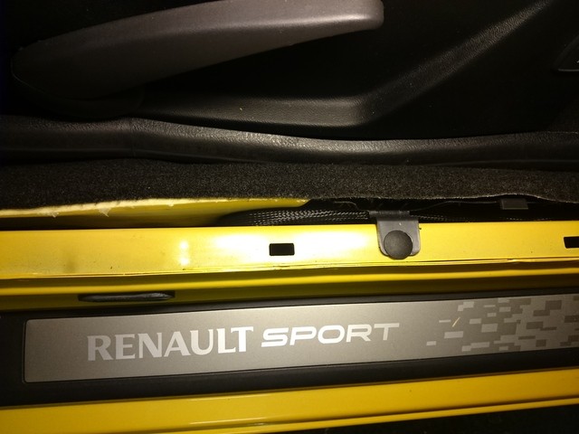
The harness was mounted from front to rear in the trunk. For a clean Installation, it had enough free retaining clips.
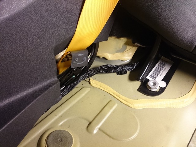
Where no retaining clip was available, self-adhesive clips were used.
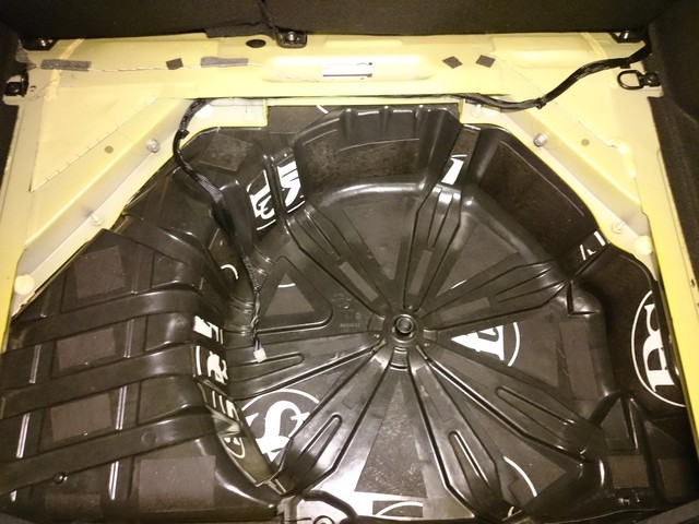
The plastic spare wheel trough was insulated with self-adhesive insulating mats.
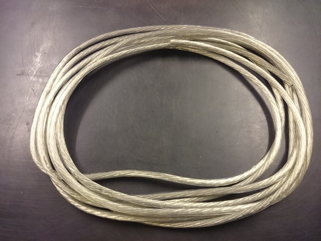
Because, the bass of the subwoofer were exchanged, the amplifier needs an external power supply from the starter battery. If the basses weren’t replaced, the power supply for the amplifier would be sufficient via the Y-adapter.
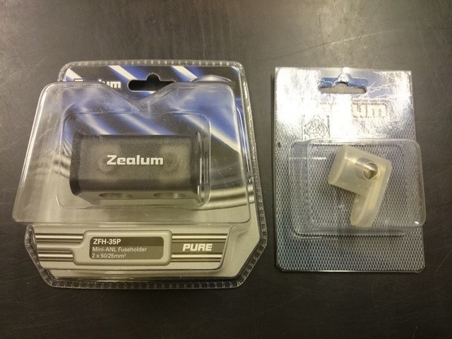
The fuse holder and the ground connection for the external power supply of the amplifier.
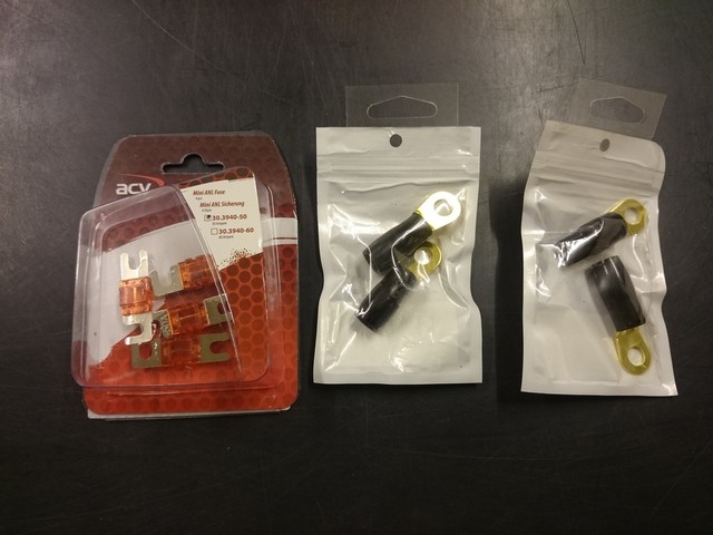
The required connectors.
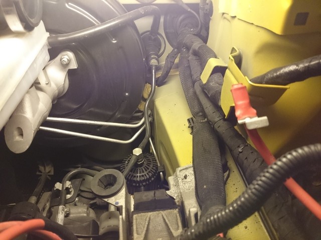
The starter battery, the battery box and the air filter box were removed, to be able to mount the plus calbe for the amplifier into the engine compartment.
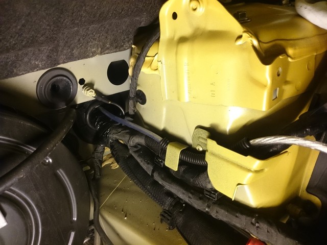
The positive cable has been installed and protected against chafing at the necessary points.
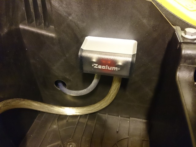
The fuse holder was mounted to the inside of the battery box.
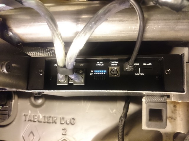
The external power supply was connected to the amplifier.
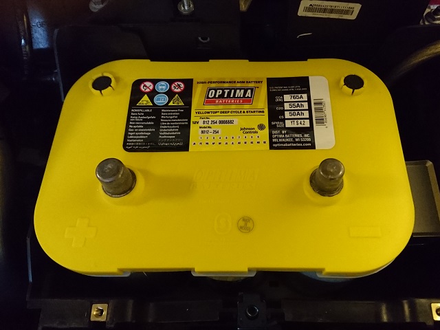
It was also installed an Optima Yellow Top starter battery.
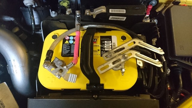
After small modifications at the connections everything fit without problems.
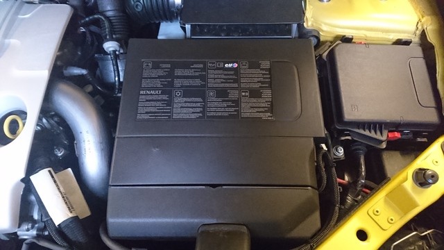
The original battery cover still fit.
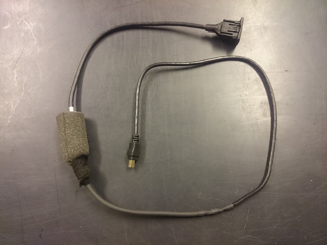
The music system will adjust with laptop and software via a USB port on the amplifier.
So that one has access to the USB port with built-in glove compartment, you need a USB extension including connector.
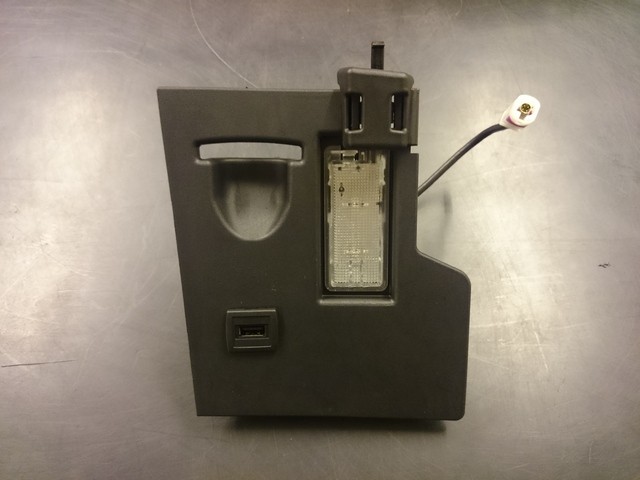
The extension connector is mounted in the glove compartment inside wall.
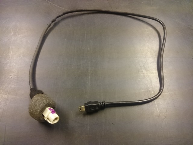
Including additional connector, if the glove compartment has to be removed once.
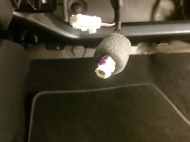
The separation point to the glove compartment.
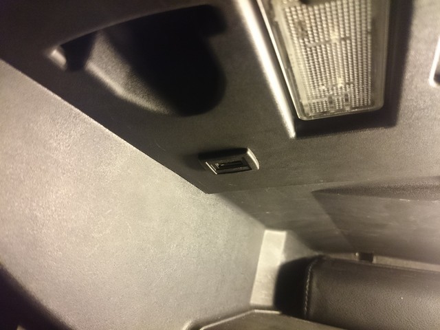
The glove compartment was reinstalled. The USB port is easily accessible.
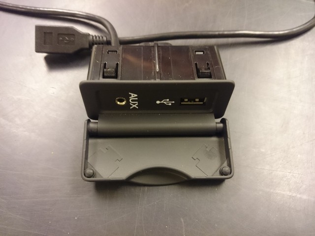
So that the iPod does not have to lie freely in the center console, because it can normally only be connected to the USB port, An iPod console was built into the center armrest compartment. The USB signals were fed into the original USB module.
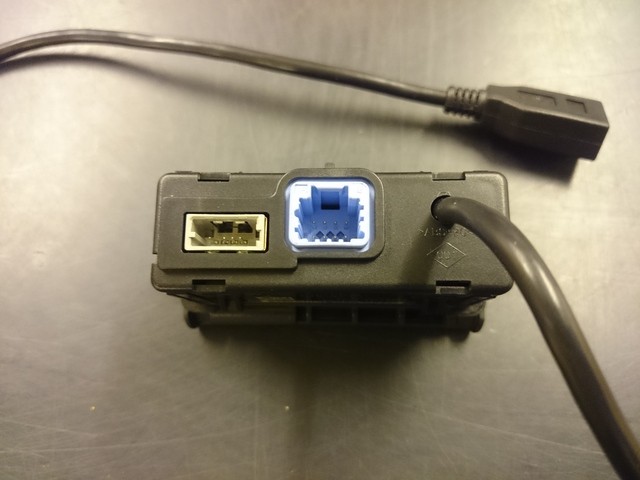
The soldered USB cable also has a USB seperation point, so that all components can be removed individually.
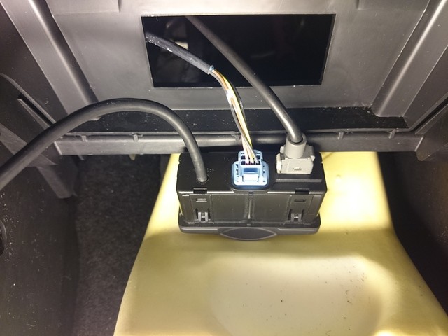
The modified USB module has been reinstalled.
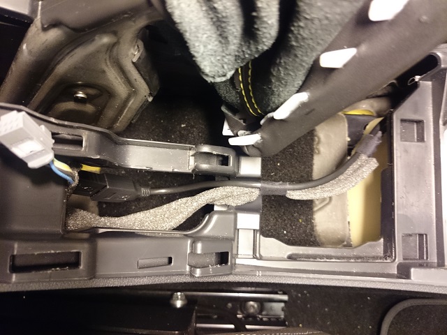
And mount the new USB cable to the back of the armrest.
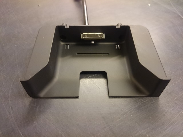
The output base for the newly made iPod console, is a component of another vehicle manufacturer.
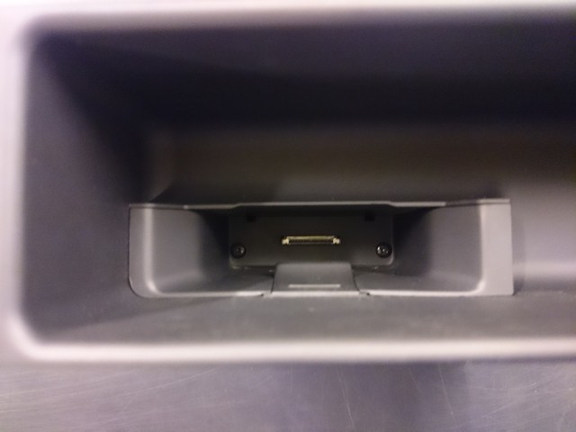
The new iPod console has the standard DIN radio mass.
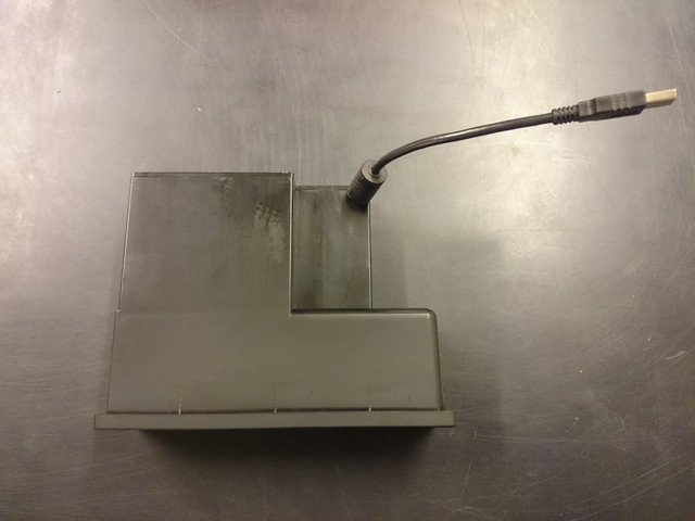
The connectors of this iPod console still had to be converted to USB.
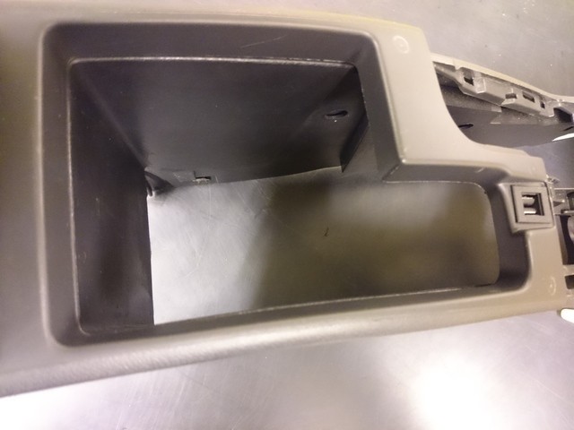
The middle armrest was dissected and cut at the required points.
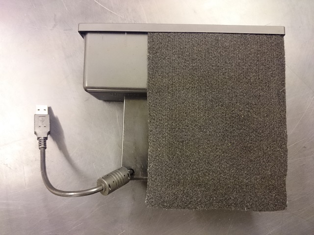
The side panel of the armrest was covered with black felt.
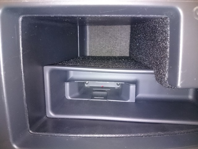
The iPod console was fitted into the middle armrest compartment.
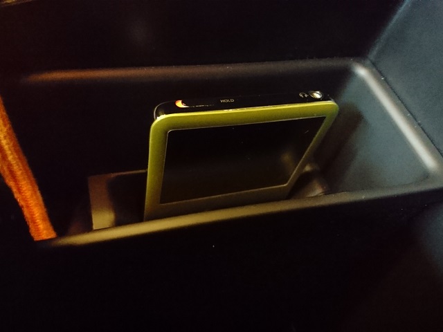
The middle armrest was reinstalled and the iPod plugged in. The OEM look exists.
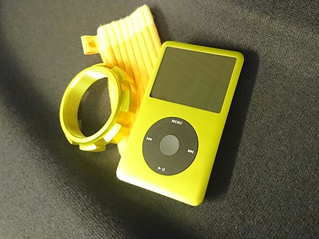
The iPod Classic 6.5G 160GB is only used in this car. So it could be anodized appropriately.
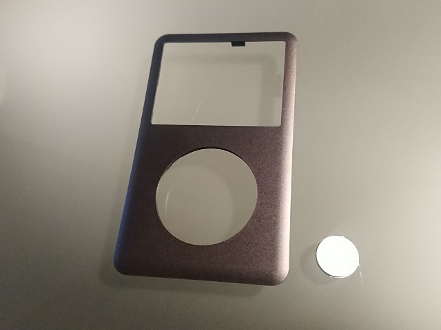
The individual parts for anodizing.
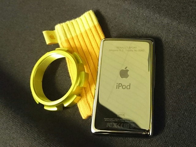
The back was also engraved matching to the car.
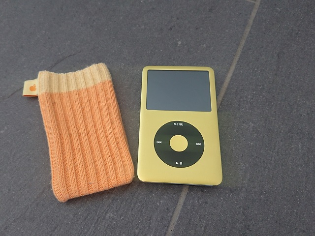
The wheel click button was subsequently anodized in yellow to match. Now the look is perfect.
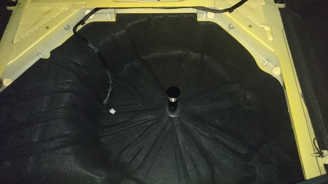
The spare tire trough was covered with felt.
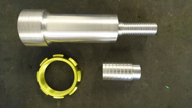
It was made a special subwoofer holder. The subwoofer is mounted with an RSC Suspension lock nut.
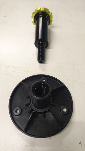
The parts were matched anodized and the aluminum thread is pressed in and glued into the lower holding plate.
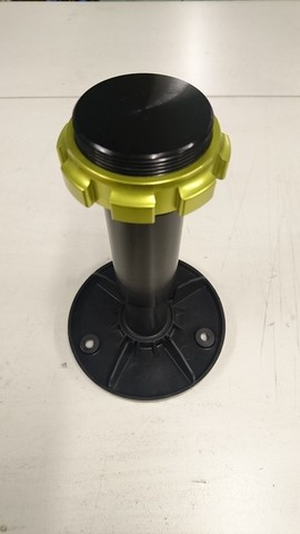
Outside the spare tire trough, the whole looks assembled like this.
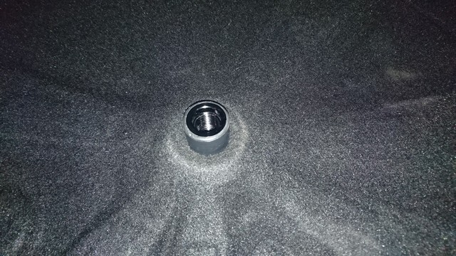
The lower holding plate with the glued-in aluminum thread was screwed from below to the spare wheel trought.

The mounting bolt was screwed into the holding plate.
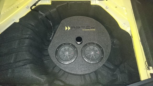
The subwoofer was plugged over and connected.
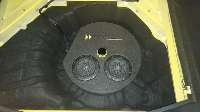
And tightened with the RSC Suspension locknut.
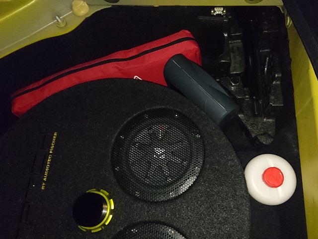
The tool and the rest of the necessary material also has place in a corner.
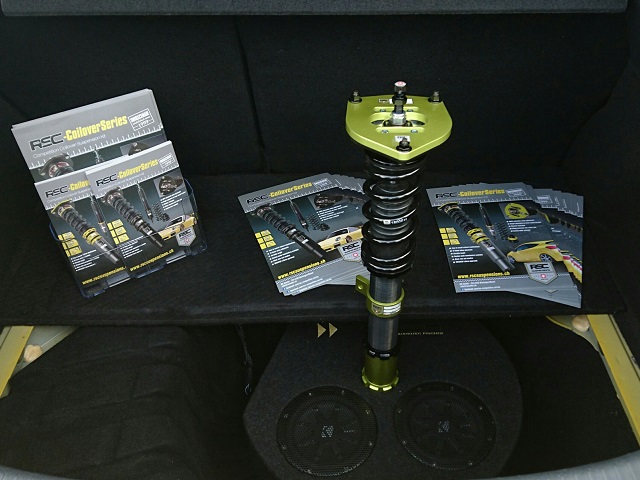
The protruding thread of the mounting bolt can be used for mounting an RSC suspension strut. A simple and practical exhibition space at meeting.
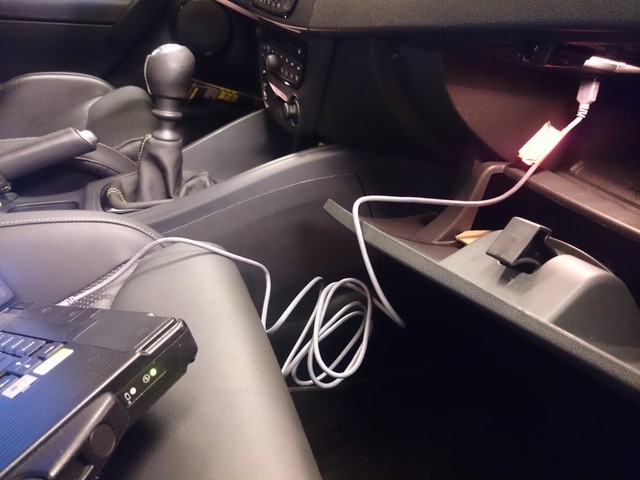
The music system could now be conveniently personally adjusted by Audio Art via the USB port provided in the glove compartment. Done.
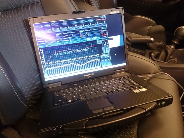
The software for the adjustment can be downloaded from the Audiotechnik Fischer website.
