Installation BPC2 With Mapping Selector Switch
Here’s described the installation of the BPC2 (chiptuning with additional box) including mapping selector switch. For an even better result in execution and end result, it was especially paid attention to some details.
Normally, the BPC2 is installed in the engine compartment near the starter battery. During this installation, the BPC2 harness has been extended to the interior by using unused original cables in the vehicle wiring harness. In addition, it was used the controller for the headlight adjustment for the diffent mapping selection. Because this vehicle is equipped with gas discharge lamps, so the regulator has not yet been installed. Thus, the system is perfectly integrated in the interior and no additional switches have to be installed.
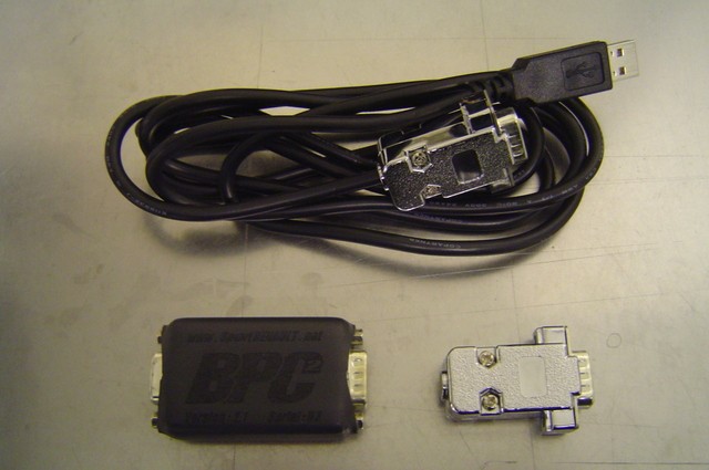
The mounting material: BPC2, program cable for the laptop, placebo plug (if the BPC2 should stay away).
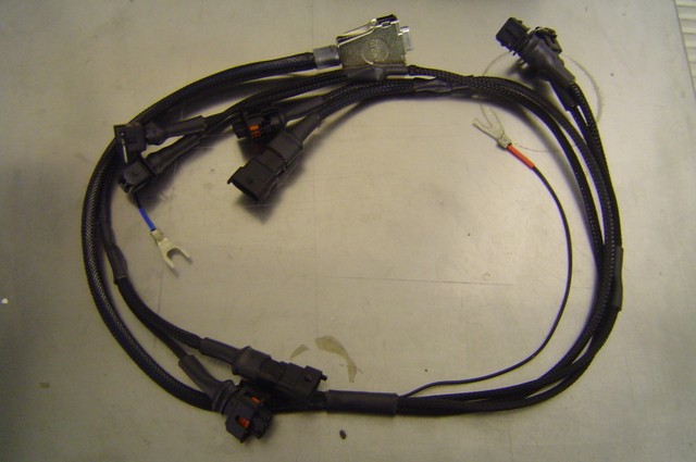
Further mounting material: The BPC2 engine harness:
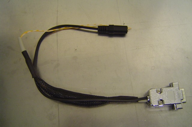
Futher mounting material: BPC2 adapter for the mapping selector switch and further outputs.
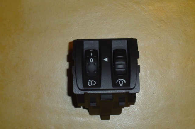
Further mounting material: The regulator for the controller for the headlight adjustment converted for the BPC2 mapping selection.
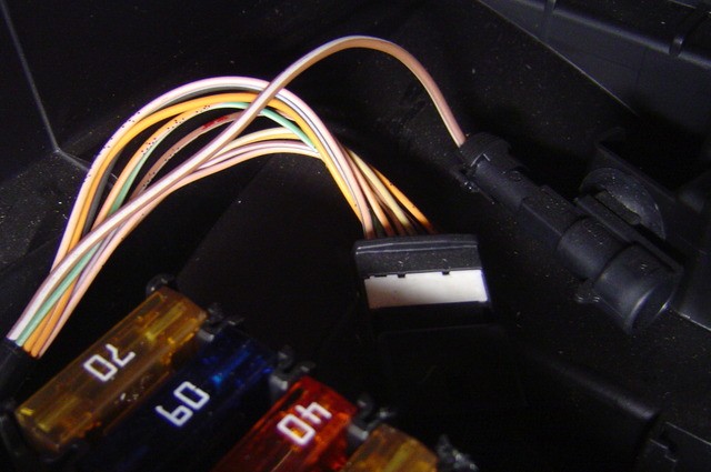
The not used harness and connectors in the electrical box in the engine compartment, which end into the interior.
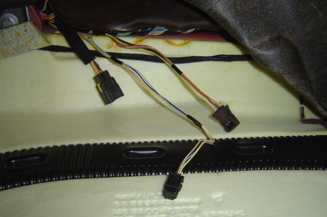
In the area of the central tunnel, the other end of the cables come out.
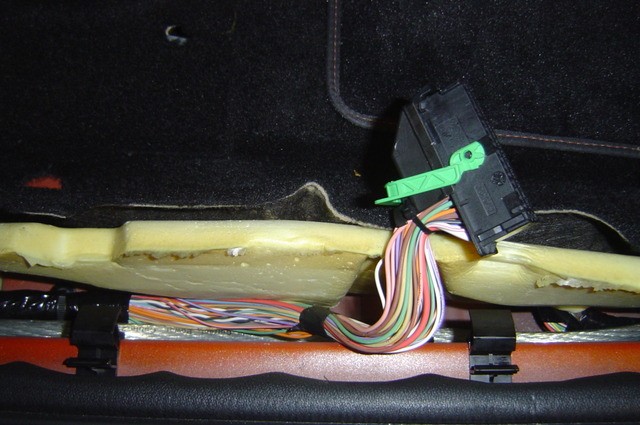
As well as under driver’s seat.
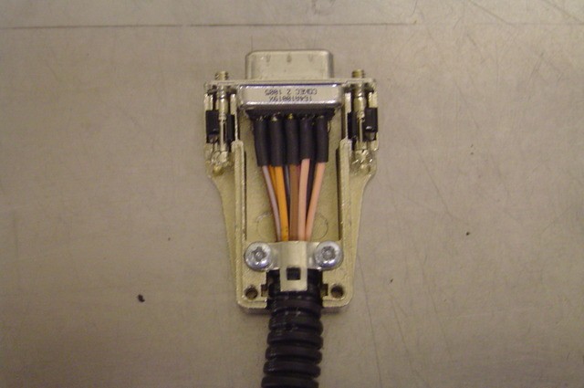
A new cable harness was made, to connect the cable ends to the installation location of the BPC2. The COM plug connections of the two BPC2 harness were soldered in here.
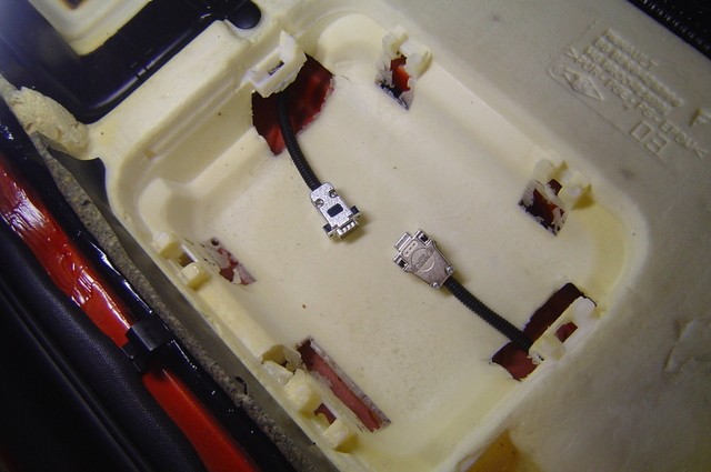
The new cable harness was inserted.
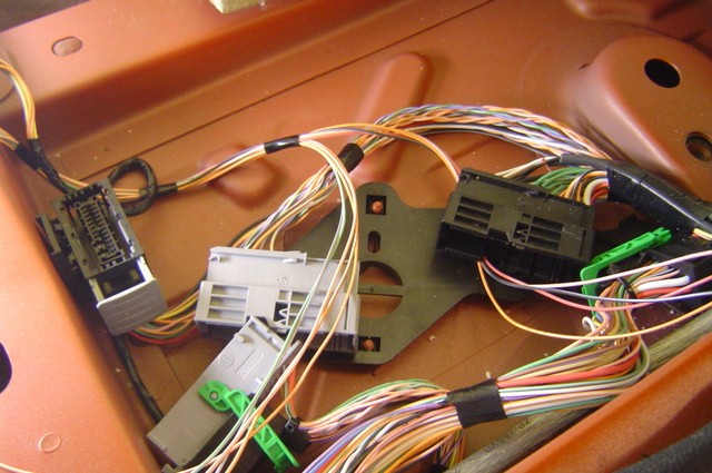
And brought together the ends of the two harness.
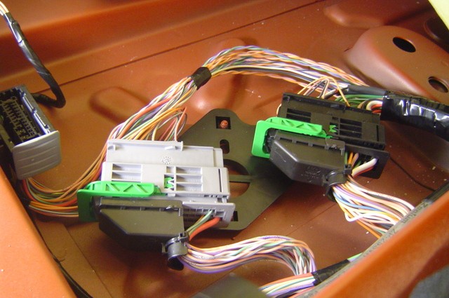
And pinned into the connector.
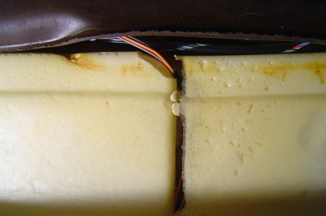
Also the cables at the central tunnel was connected.
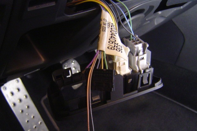
At the same time, the cables to the controller of the headlight adjustment (BPC2 mapping selector switch) were also integrated into unused cables of the original harness, and can be found again under the dashboard at the BPC2 mapping selector switch, formerly the controller of the headlight adjustment.
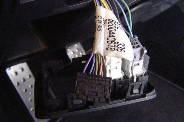
The pins were pinned in on the connector of the controller of the hedlight adjuster / brightness control of the dashboard lighting (same connector housing).
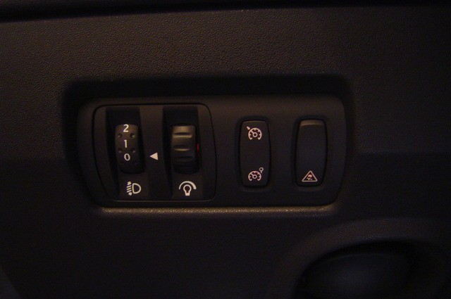
The switch unit has been installed. The position 4 of the adjusting wheel was internally mechanically blocked, because the BPC2 can store 4 mappings.
Position 0 = OEM Mapping (Placebo)
Position 1 to 3 = Various mappings, freely selectable
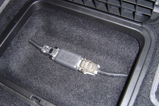
The floor carpet was mounted again. The two BPC2 COM connections now end in the compartment in the floor carpet on the driver’s side. The BPC2 or the placebo plug can be attached to the ground carpet with velcro fastener. This isn’t absolutely necessary.
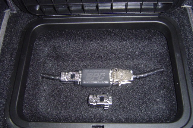
So it can remove comfortobal and conveniently the BPC2 for programming, or disconnect and plug in the placebo plug, without having to open the bonnet.
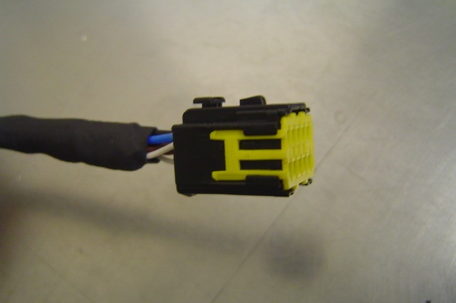
On the BPC2 engine harness was mounted, instead of the previous COM connector, the matching connector for the OEM harness, that ends in the electrical box in the engine compartment.
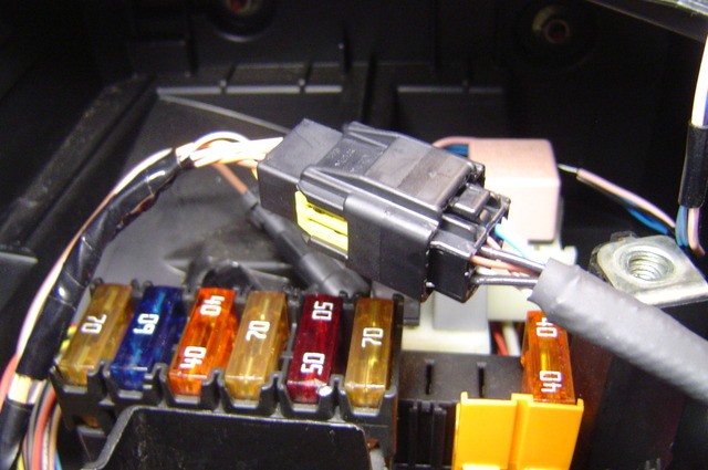
The BPC2 engine harness was connected in the electrical box with the OEM harness, and the connectors at the other end, as well as with a normal BPC2 engine harness, with the engine periphery.
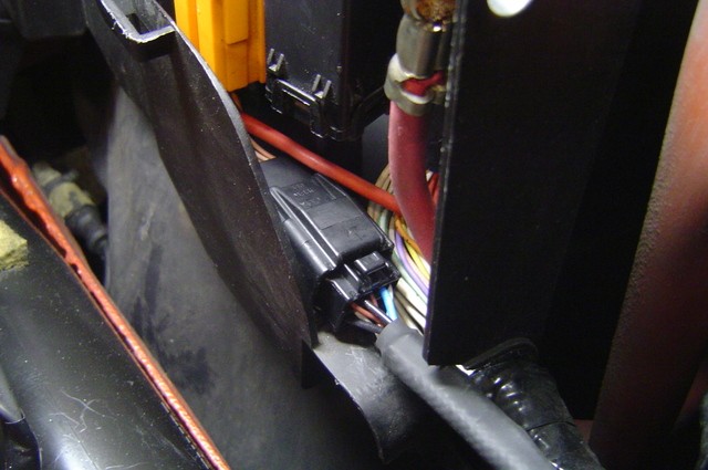
The connector to the interior in the electrical box in the engine compartment.
