Conversion L7X 760 To L7X 762 Engine With “Trophy” – devil Exhaust
Here’s described the installation of the engine from L7X 760 from the Renault Sport Clio V6 Phase 1 to the L7X 762 engine from the Phase 2, inclusive the “Trophy” – devil exhaust system. For an even better result in execution and end result, it was especially paid attention to some details.
This engine conversion was converted the L7X 760 Phase 1 engine with all the different parts of the L7X 762 Phase 2 engine. In addition, the intake was polished, the hydraulic power steering replaced against an electrohydraulic version, and the complete “Trophy” exhaust system was added. The ECU were finally mapped to all rebuilding measures. The result is impressive: From the OEM, theoretical 230HP and 300Nm, which really hardly reaches a OEM phase 1, were real 270PS / 310Nm!, measured on a neutral dynotest from a official automobil club. Again, theoretical 15Ps more, than a OEM Phase 2 (255HP), Wwhich can also be assumed, to spread regularly 5% downwards.
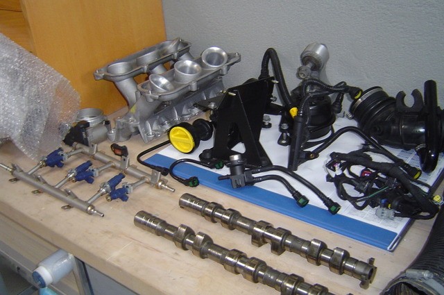
The needed L7X 762 engine parts.
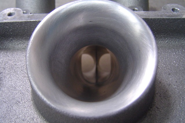
The intake were polished, and the transitions balanced.
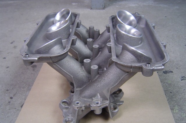
The upper L7X 762 intake bridge with the 6 funnels.
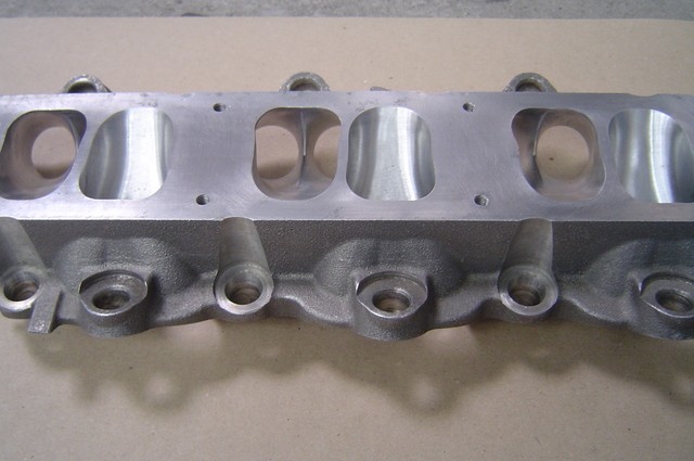
The under intake bridge.
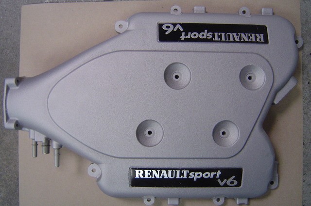
The intake manifold cover was glass-beaded.
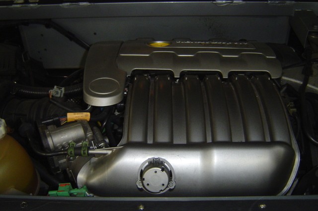
The output base: The L7X 760 engine.
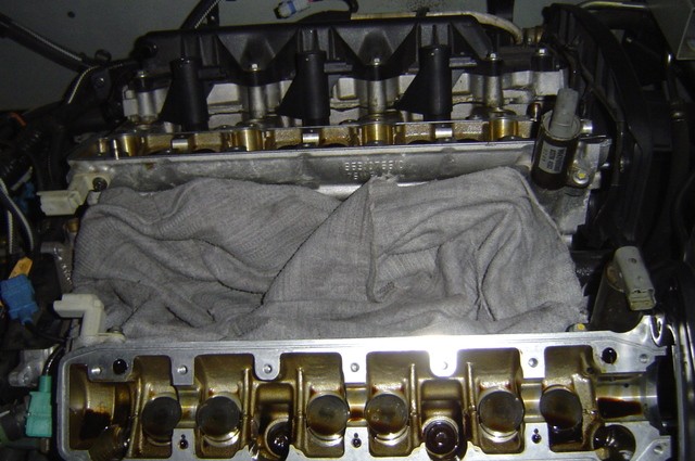
All L7X 760 Phase 1 engine parts were expanded.
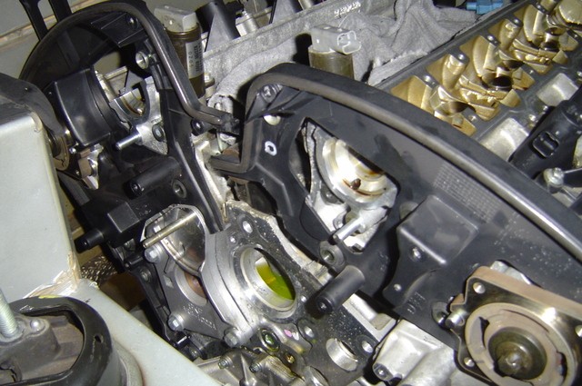
The belt, all rollers and the water pump were also replaced.
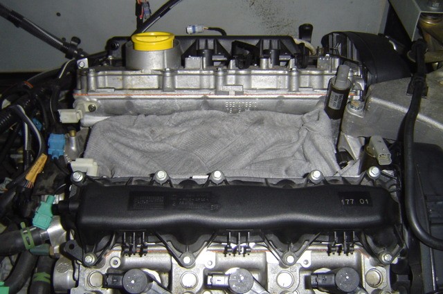
The engine mechanics with the L7X 762 Phase 2 camshafts were reassembled.
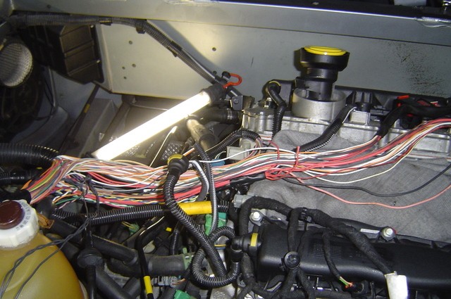
The harness was changed. This isn’t essential for the conversion to L7X 762 Phase 2 motor. The Lambda probe cables have been relocated for the “Trophy” devil exhaust system.
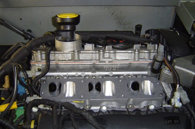
The harness was relocated and the lower L7X 762 phase 2 intake manifold, including the venting lines, was mounted.
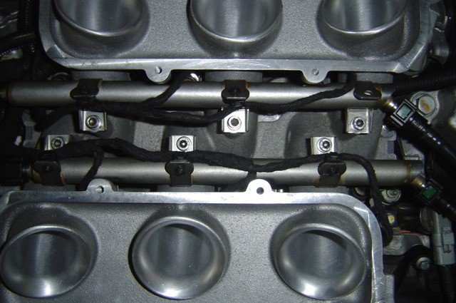
The middle L7X 762 Phase 2 intake manifold including fuel supply was installed.
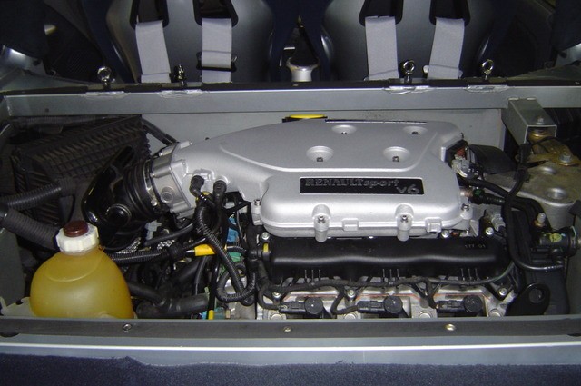
The remaining L7X 762 phase 2 parts were installed: The upper intake manifold including various pipes, the throttle including the intake hose and the airbox with filter. Done.
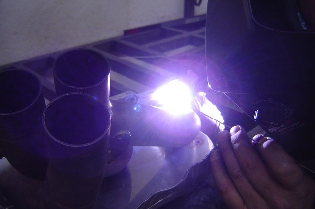
The adaptation of the “Trophy” – devil exhaust system started.
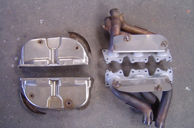
Firstly, the manifolds were adapted for road-compatible use, and fitted with the shielding plates of the series manifolds.
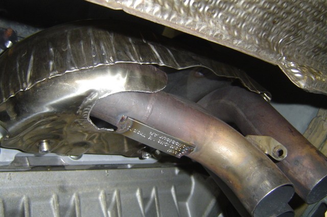
The “Trophy” exhaust manifolds have been installed.
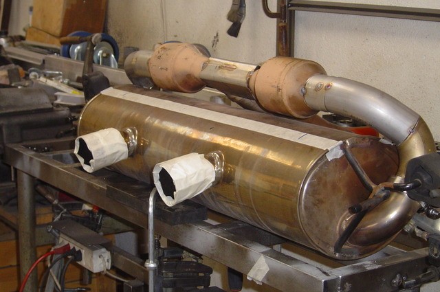
The “Trophy” metal catalyst were adapted to the devil rear muffler.
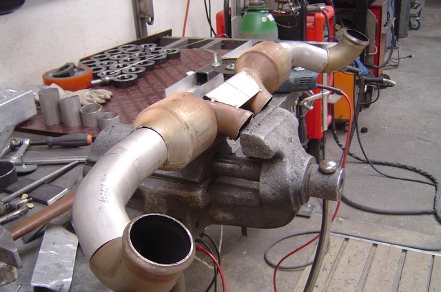
The parts are ready to weld together.
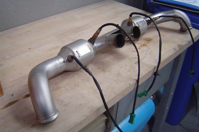
The probe connections were welded, and then the entire unit was glass-beaded.
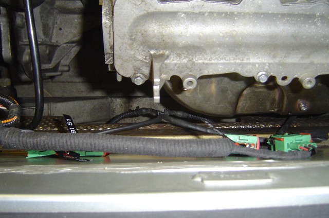
After the new installation, all four probe connections end at the rear panel of the engine compartment at the new location of the probes.
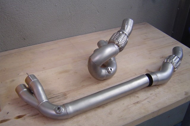
The both downpipes with integrated flex were made, and each equipped with an additional measuring port on both cylinder banks for mappings. Then, these parts were also glass-blown before assembly.
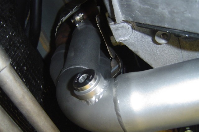
The downpipe of the cylinder bank 1 has been mounted.
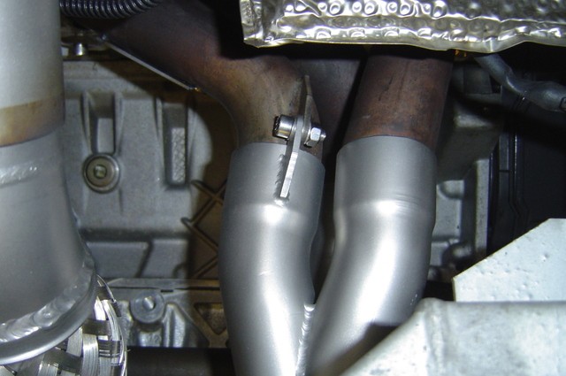
Also the downpipe of the cylinder bank 2.
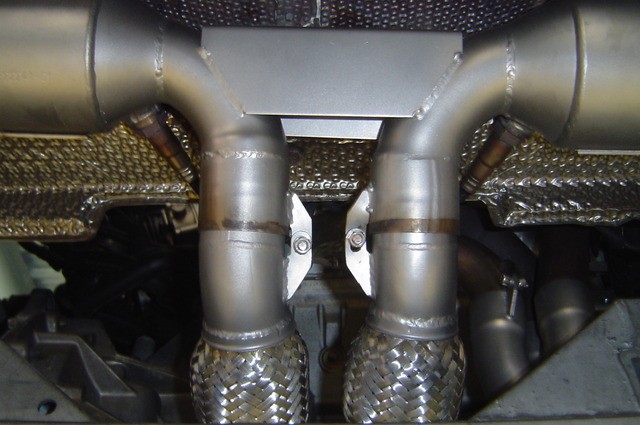
Both downpipes were connected to the metal catalyst unit.
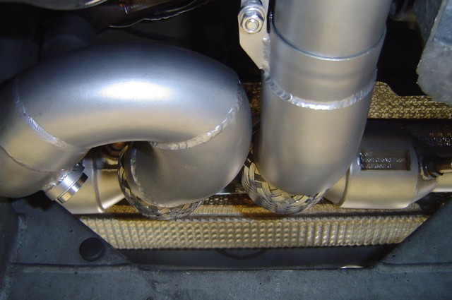
Detail view.
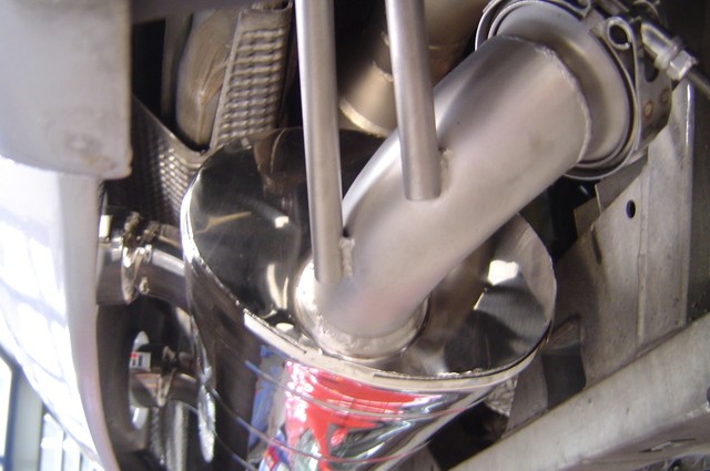
The devil rear silencer was glass-beaded, then polished and mounted.
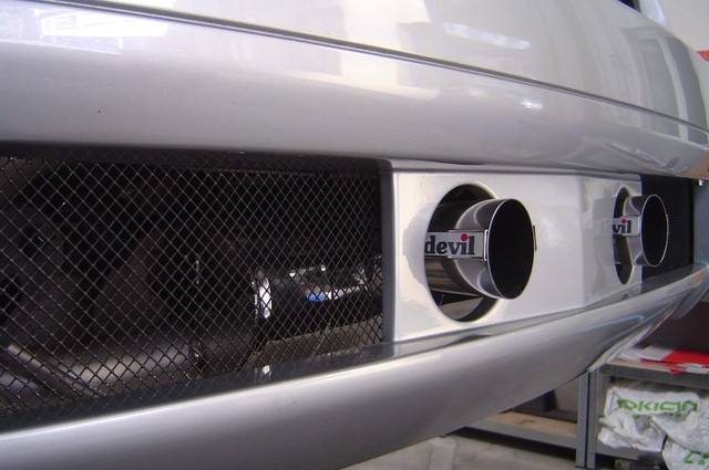
The devil tailpipes still got new stickers. Done.
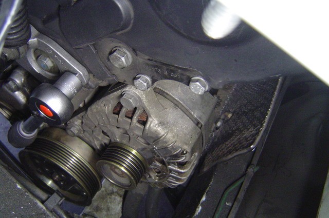
The standard hydraulic servo steering system has been completely extended. First the hydraulic pump.
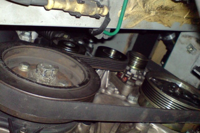
Then a shorter belt was installed, which compensates the shorter belt circumference without hydraulic pump.
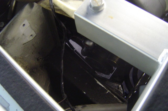
The reservoir of the OEM power steering was also removed.
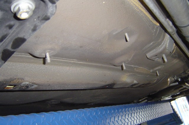
Also the servo lines under the vehicle, which lead forward to the servo steering, have been removed.
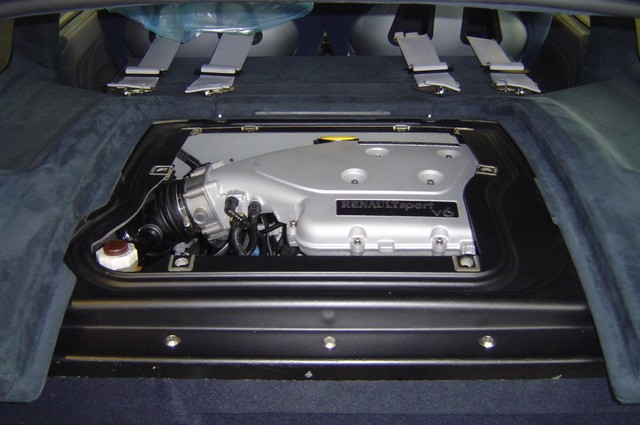
In the engine compartment everything was ready and the engine covers could be re-assembled.
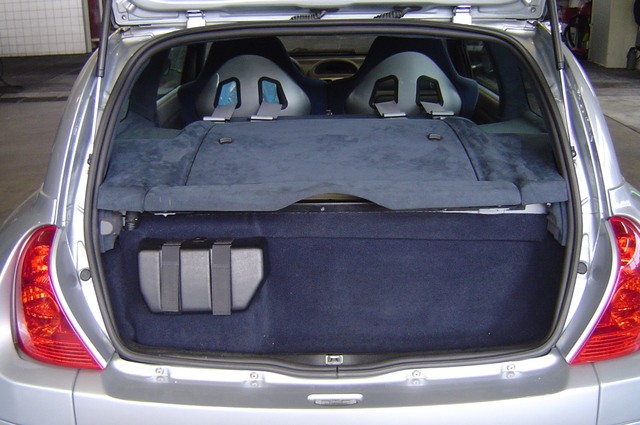
And the alcantara covers were also mounted.
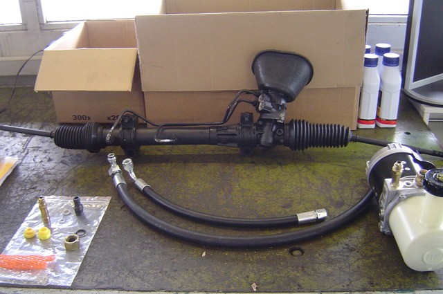
The parts required for the conversion to electrohydraulic servo steering. The steering gear in this Picture was only required for adjustment purposes.
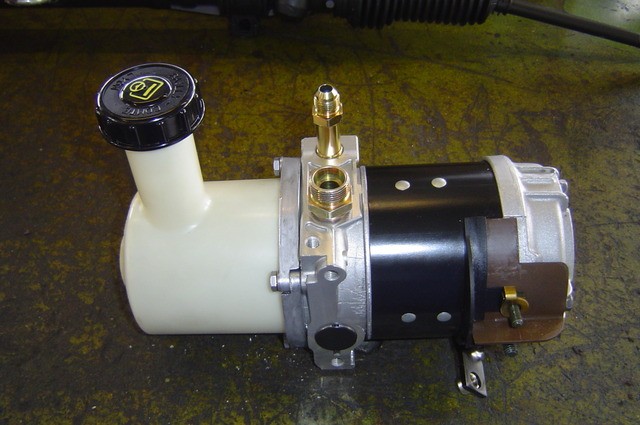
The electro hydraulic servo pump from the V6 Trophy racing car.
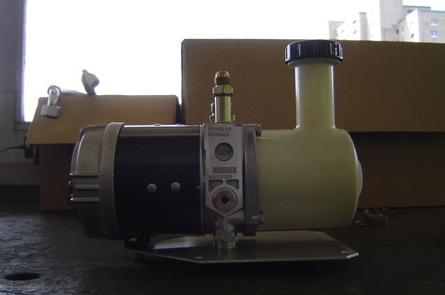
A holding plate was customaded.
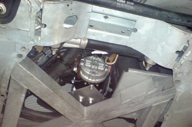
The electrohydraulic servo pump was screwed with the support plate and rubber vibration damper to the front axle.
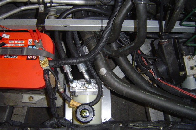
The hydraulic hoses between pump and steering gear were installed.
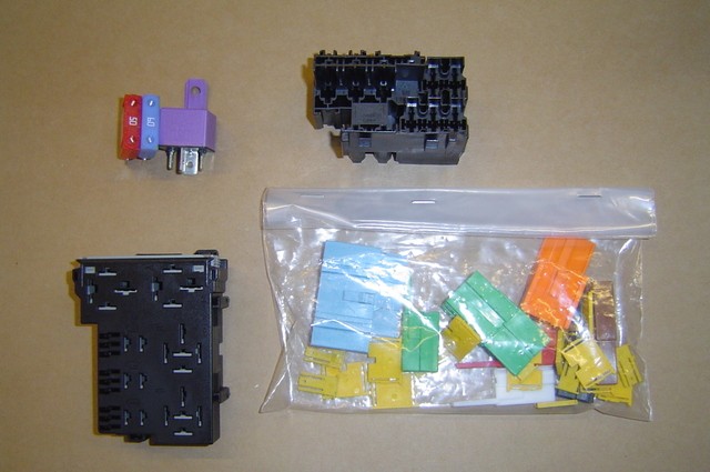
The corresponding fuse and the required relay were added to the original relay and fuse holder at the front left behind the headlight. For this reason, there were new fuse holders, which had space for additional components.
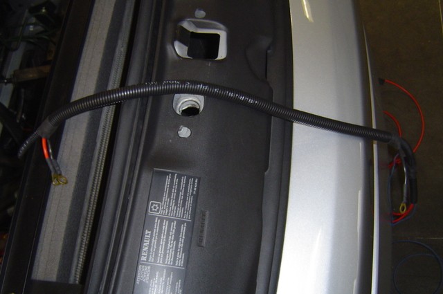
The harness for the electrohydraulic servopump was made suitable.
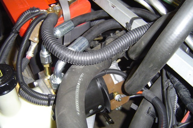
The made harness was mounted.
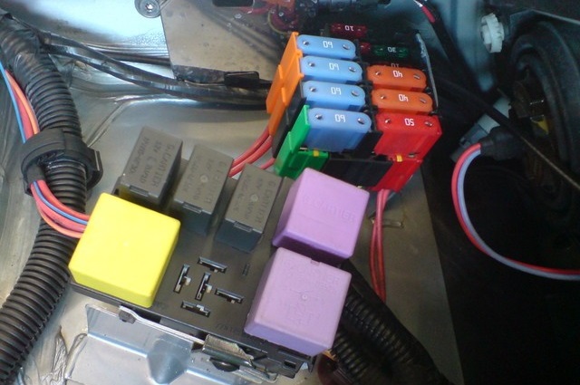
The new relay carrier and fuse holder with more slots was installed. The relay for the electrohydraulic servopump (purple) is located at the top (small) and the fuse (blue 60A) at the bottom in the green slot.
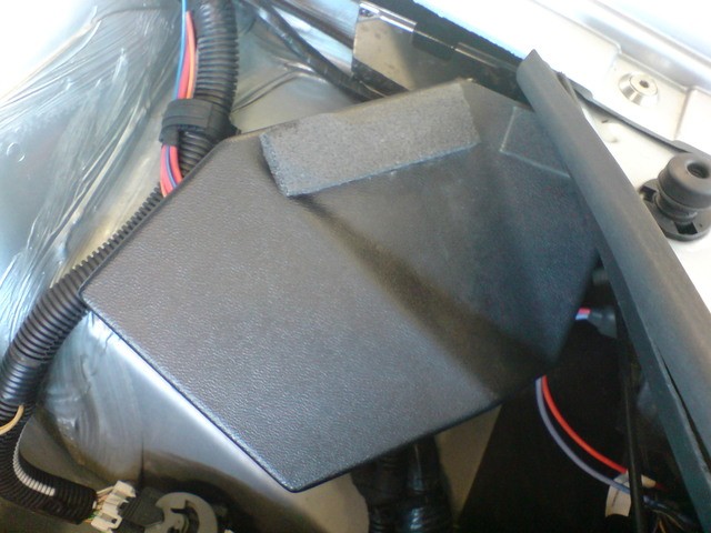
The original cover still fits.
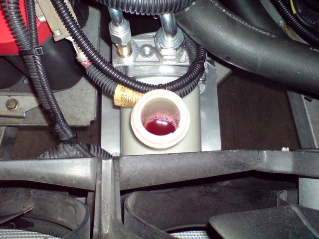
The ATF was filled in.
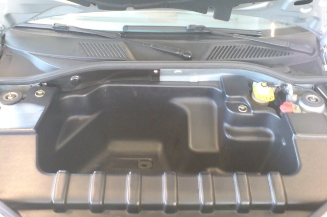
The trunk tub was reinserted. Done.
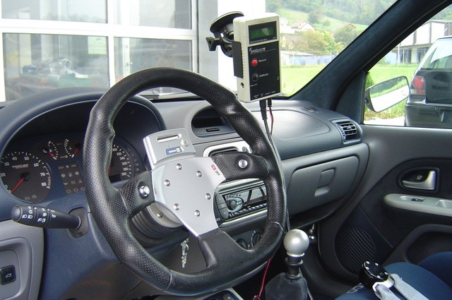
The ECU were first mapped on the road under real conditions.
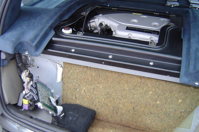
For the new mapped EPROM, a socket was soldered to the board.
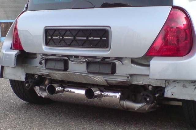
For the dyno tests the Clio V6 had to be raised by 20mm and the rear bumper was unscrewed for safety.
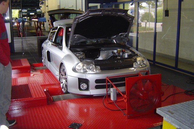
On the dyno.
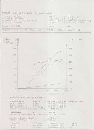
The result is impressive: 270.64 HP / 199 kW / 310 Nm with 98 octane.
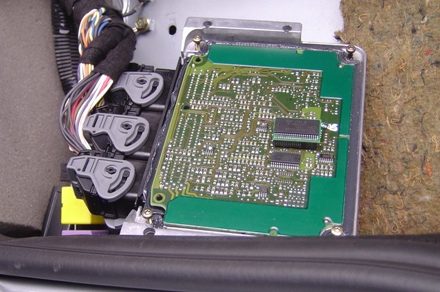
The EPROM socket remained on the board to be ready for later changes.
.
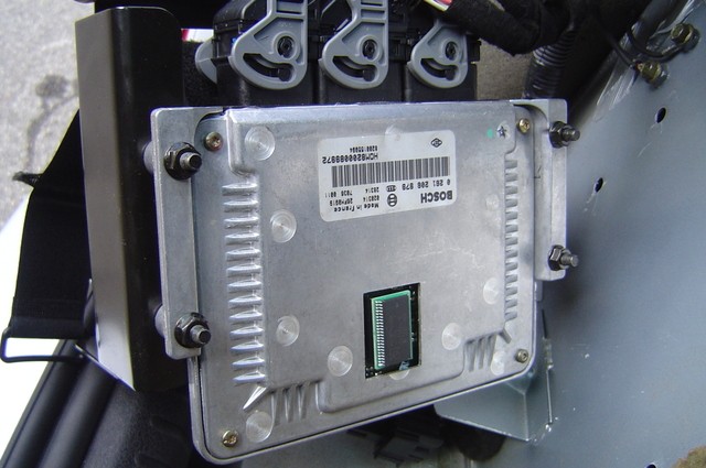
Therefore the cover of the ECU got a service opening.
The RS Center Videos From The Conversion
Engine
Exhaust System
Power Steering
ECU Mapping
Exhaust System
Dyno Test
